One of the main methods of joining metal elements is the welding process. Welding is a special process and requires precise determination of process parameters. One important aspect is determining the requirements for the weld. The marking of the weld in the drawing and its names are strictly defined. It is accepted in the industry that welds are divided into three categories: butt welds, fillet welds and others. There are also a number of subcategories of welds.
Types and symbols of weld marking in the drawing
- Unilateral inguinal
- Inguinal bilateral
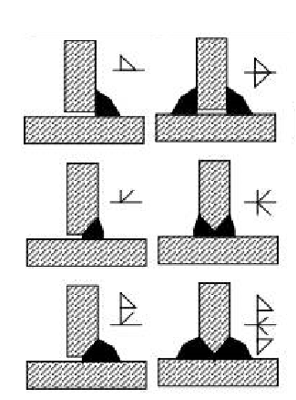
- Frontal unilateral
- Frontal double-sided
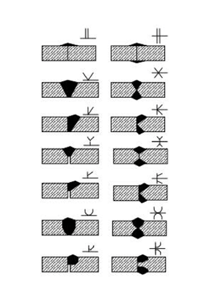
- Marginal
- Dorsal
- Open-hole

Method of marking the weld in the drawing
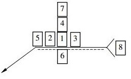
Welds are marked in a specific way in the drawing, their characteristics are defined by 8 points. It is common to see less information in a drawing (4-5 points) because it is sufficient for description. A detailed description of the points with an illustration below
- Weld symbol
- Dimension – cross-section (thickness)
- Dimension – longitudinal section (weld length)
- Additional symbols: e.g. identification of the weld face
- Additional signs: e.g. a weld made on a closed circuit
- Additional signs: e.g. underwelded weld, welded with a washer
- Dimensions of the weld edges (inclination angle, spacing between elements, etc.)
- Symbols showing: e.g. weld number, welding method, weld quality, inspection method, welding instruction, etc.
Method of marking weld quality control methods in the drawing
When special non-destructive inspection of a weld is required, it is necessary to include this information in the weld description on the drawing. The test method is then specified in point 8 by a two-letter description. Below is a “decipher” of possible descriptions:
• VT – visual examination of the weld
• UT – ultrasonic testing of the weld
• PT – penetrant testing
• RT – radiological tests
• MT – magnetic particle testing
• LT – tightness tests
• ET – eddy current tests
Thanks to this condensed compendium of knowledge, reading welds in technical drawings will be easier and simpler.
Example of a weld in a technical drawing
Depending on the design organization, the amount of information about welds may vary. Nevertheless, the standards presented above must be maintained. Below is an example of a weld description
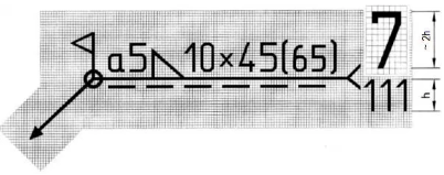
Example of weld marking: interrupted welded seam [10×45(65)], in which 10 sections of a fillet weld (L) should be made with a thickness of a = 5 mm and a length of one section l = 45 mm with a gap between them e = 65 mm. The weld is to be made around the entire circumference (O) during assembly (<|). The seam should be made using the arc method using a coated electrode (111), and the weld has the symbol 7.