When working in engineering and technical industries, the ability to read technical drawings is essential. When choosing education in fields such as machine operators, welders, mechanics, mechatronics or robotics, part of the school classes will be devoted to these topics. Using the compendium of knowledge developed below, you can now learn the specifics of technical drawings and test your skills in this field. When you start your adventure with technical professions, your knowledge of markings, tolerances and descriptions will be verified at every step. The decisions you make will be based on what you can read from the technical drawing.
Technical drawing as a form of communication
Drawing is the basic production documentation in almost every industry, from mass production of toys to the production of airplanes and space shuttles. Establishing universal principles of creation and describing the drawing allows you to clearly convey exact requirements and data regarding the product.
Few people realize it, but technical drawings are an excellent communication tool between engineers, designers and the industry.
Drawing enables understandable communication even between people who do not speak the same language. On the other hand, it requires learning the principles of reading and understanding technical drawings. In order to ensure the universality of technical documentation, a standard has been established that defines the rules for recording technical drawings.
Drawing of technical foundations
A technical drawing, regardless of the product or industry, should have a universal layout. In the drawing, you will most often find a “dimensioned” product as well as notes and tables. Due to the information recorded, the technical drawing area is divided into:
- information table
- revision table
- table with BOM (bill of material)
- notes and specifications
- letters and numbers indicating the location (e.g. D3)
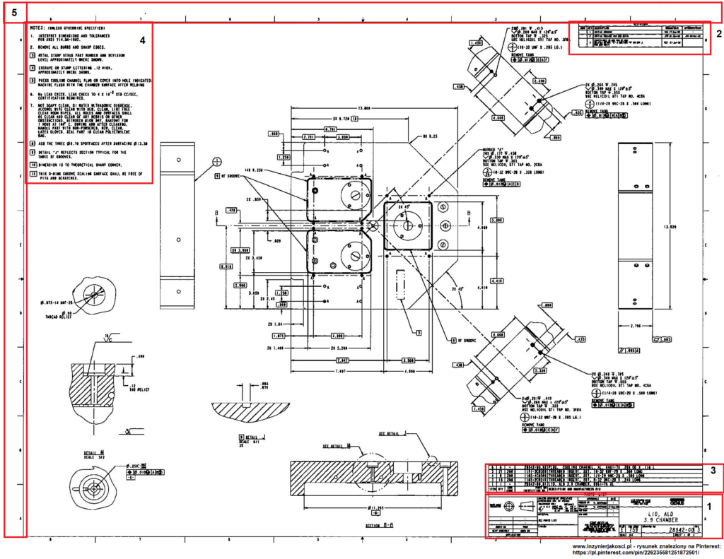
Technical drawing – information table
The table, usually located in the lower right corner, contains information about the creator of the drawing and basic information about the product. You will usually find there the name of the company, sometimes its address and the name and surname of the engineer who created the drawing. Additionally, the table should contain information about the part number, its utility name, drawing revision, scale, dimensional units and drawing dimensions.
Additionally, there is also very important information about projection methods, which can radically change the way a drawing is read. You may meet in your career with two styles of drawing preparation: American and European. They differ from each other precisely in the projection method. The graphic below should dispel your doubts

Technical drawing – revision table
The next table in the drawing, identified in the entry as number 2, is usually located in the upper right corner. It defines the history of changes made to the drawing. Every change in the drawing requires a change of revision attribution. The changes may be significant, such as changing of a critical dimension, tightening of the tolerance, etc., or basically only tiny corrections, e.g. for older drawings, so-called remastering is performed. This table usually contains the date of change, type of change and revision symbol. Revisions can be marked numerically or by a letter (added according to alphabetical order).
Technical drawing – BOM table
This table appears only in products consisting of more than one element. In simple terms, it is a list of parts that make up a given product. The table usually contains component part numbers. Most often, notes are located in the lower left corner, but this is not a rigid rule. Substantially,
in this case, knowledge of foreign languages is useful. In the notes, the engineer includes detailed information about the material, the processes required to produce the item and the inspection methods. Typically, required specifications and instructions for each control process and method are provided.
Technical drawing – letters and numbers defining the area
The drawing is divided on the x-axis by numbers at equal intervals, and on the axis Y in equally spaced letters. This creates a coordinate grid that makes location easier and directs the interlocutor to a given area. It is much easier to request verification of a dimension in C5 that responds to a dimension 24mm, rather than asking to find a dimension 24mm in the entire drawing.