Do you know what geometric tolerance symbols are? When it comes to ensuring product quality, these are the most important elements of a technical drawing. Any dimension outside the tolerance indicates a nonconformity. You must be able to interpret measurement results based on the tolerances of the technical drawing.
What are geometric tolerance symbols?
When designing parts, the engineer creates a technical drawing and includes key dimensions onto it. These are called nominal dimensions. It is impossible to produce a series of products according to nominal dimensions only.
Therefore, deviations from the dimension are used, which are referred to as dimensional tolerances. These may apply to various elements and areas of the product. Therefore, geometric tolerance symbols are defined.
What are they? These are all “figures” that appear next to a numerical value and refer to a specific product characteristic. In practice, there are several symbols used that mean the same thing all over the world. Regardless of whether the drawing was designed in Japan or in the USA. Understanding and remembering what each symbol means will help you to interpret measurement results. Geometric tolerance symbols are divided into four categories:
- Shape
- Direction
- Locations
- Runouts
Geometric tolerance symbols – definitions and examples
Knowing these 14 symbols will allow you to freely interpret technical documentation. Under each definition you can review graphical interpretation of explained definition.

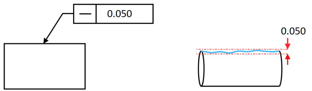
– straightness tolerance – tolerance limited by parallel lines spaced from each other by the tolerance value.

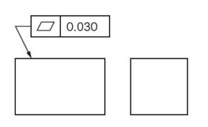
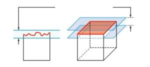
– flatness tolerance – tolerance limited by two surfaces spaced from each other by the tolerance value.
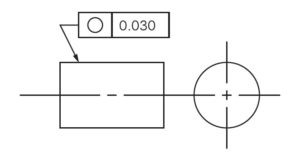
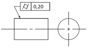
○ – roundness tolerance – tolerance limited by two, large and small circles, where the difference in radius is the tolerance value.

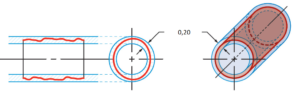
⌭ – cylindricity tolerance – tolerance limited by two coaxial cylinders with a difference in base radius that create tolerance value.
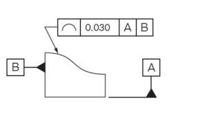
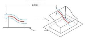
⌒ – shape tolerance of the determined outline – tolerances limited by circles where the difference in radius is the tolerance value.
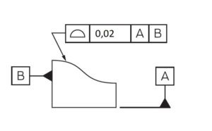
⌓ – shape tolerance of the designated surface – tolerance limited by larger and smaller spheres, where the radius of the spheres differ by the tolerance value.

⟂ – perpendicularity tolerance – the tolerance zone is limited by two parallel surfaces at a distance from each other by the tolerance value. These lines are perpendicular to a given base.

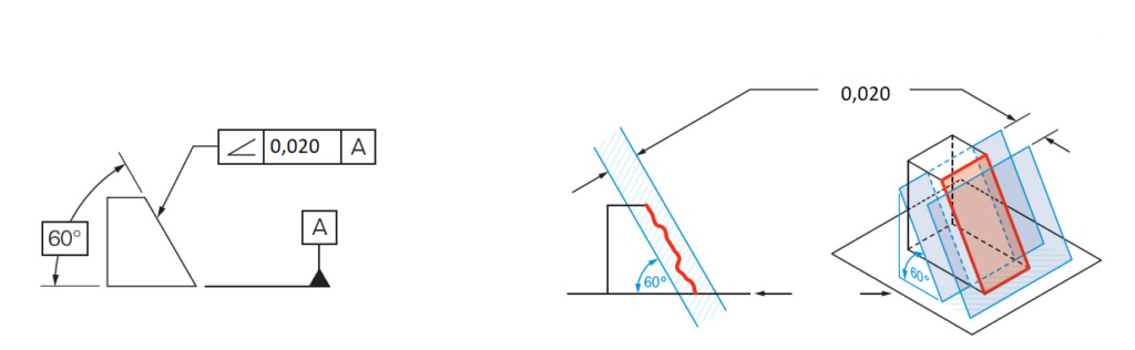
∠ – inclination tolerance – the tolerance zone is limited by two surfaces separated by a tolerance value, inclined at an angle to the nominal value.
∥ – parallelism tolerance – the tolerance zone is limited by two parallel surfaces separated by a tolerance value, which are parallel to the designated base.

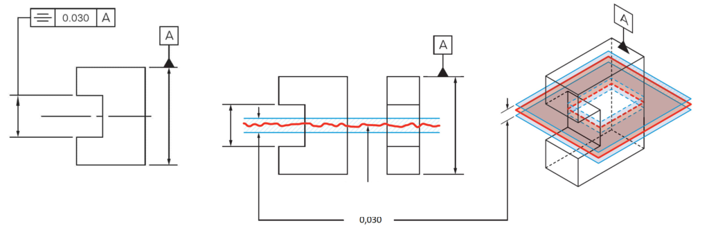
⌯ – symmetry tolerance – the tolerance zone is limited by two parallel surfaces separated by a tolerance value and symmetrical to the designated axial base or surface base.
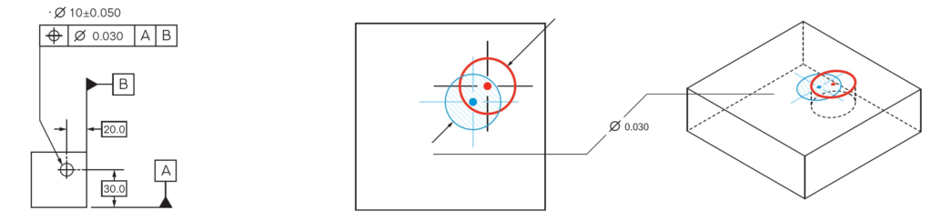
⌖ – position tolerance – tolerance zone limited by a cylinder with the diameter of the tolerance value, where the center of the cylinder is located at the point of the nominal position value.
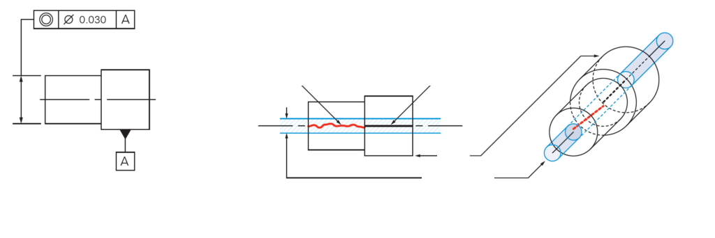
◎ – coaxiality/concentricity tolerance – the tolerance zone is limited by a cylinder with the diameter of the tolerance value, where the axis of symmetry of the cylinder coincides with the nominal value.
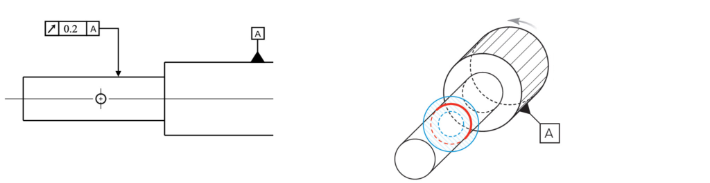
↗ – radial/axial runout tolerance – the tolerance zone on the measurement plane is limited by two concentric circles with a radius difference of the tolerance value.
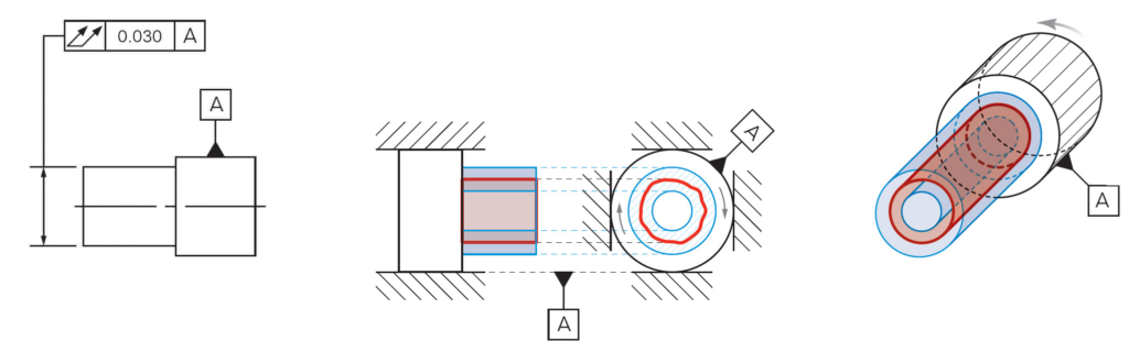
⌰ – total radial/axial runout tolerance – tolerance zone defined by two concentric cylinders with a difference in radius of tolerance value.
Geometric tolerance symbols infographic
Summary A good knowledge of geometric tolerance symbols will greatly facilitate your work with technical drawing. You will be able to say with a clear conscience whether, for example, the flatness or perpendicularity of a given product dimension is consistent with the drawing or not.